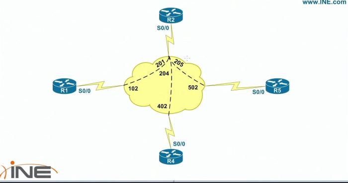
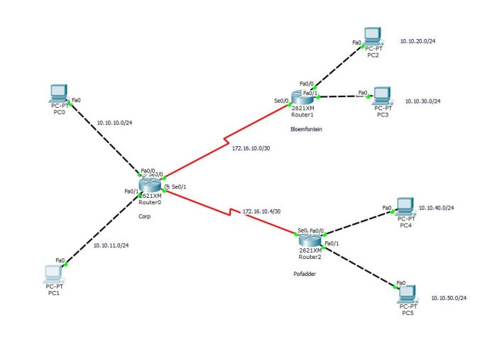
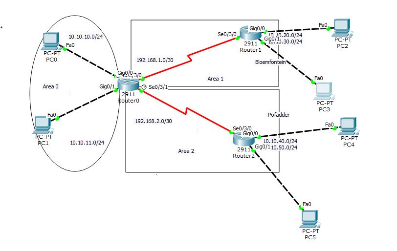
This is a sample configuration of OSPF multi area.

Router 0, called Corp, is the ABR. Bloemfontein is area 1, and Pofadder is area 2
If configured correctly, any PC in any area can ping any other PC.
———————————————————————————————
Router 0 configuration: (once you have set up the addressing scheme)
router ospf 1
log-adjacency-changes
network 10.10.0.0 0.0.255.255 area 0
network 192.168.1.0 0.0.0.3 area 1
network 192.168.2.0 0.0.0.3 area 2
Note that the 192.168.1,etc area has a /30 address, which means a 255.255.255.252 subnet mask, which, by the simple formula of 255-252, gives you the final octet of 3 when configuring netmask in network statement, ie 0.0.0.3
———————————————————————————————–
Router 1 (Bloemfontein) configuration:
router ospf 1
log-adjacency-changes
network 192.168.1.0 0.0.0.3 area 1
network 10.10.20.0 0.0.0.255 area 1
network 10.10.30.0 0.0.0.255 area 1
———————————————————————————————–
Router 2 (Pofadder)
router ospf 1
log-adjacency-changes
network 192.168.2.0 0.0.0.3 area 2
network 10.10.40.0 0.0.0.255 area 2
network 10.10.50.0 0.0.0.255 area 2
——————————————————————————————-
OSPF fault finding commands
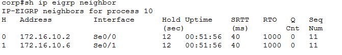
corp#sh ip ospf neighbor
Neighbor ID Pri State Dead Time Address Interface
192.168.1.2 0 FULL/ – 00:00:39 192.168.1.2 Serial0/3/0
192.168.2.2 0 FULL/ – 00:00:39 192.168.2.2 Serial0/3/1
—————————————————————————–
corp#sh ip ospf
Routing Process “ospf 1” with ID 192.168.2.1
Supports only single TOS(TOS0) routes
Supports opaque LSA
It is an area border router
SPF schedule delay 5 secs, Hold time between two SPFs 10 secs
Minimum LSA interval 5 secs. Minimum LSA arrival 1 secs
Number of external LSA 0. Checksum Sum 0x000000
Number of opaque AS LSA 0. Checksum Sum 0x000000
Number of DCbitless external and opaque AS LSA 0
Number of DoNotAge external and opaque AS LSA 0
Number of areas in this router is 3. 3 normal 0 stub 0 nssa
External flood list length 0
Area BACKBONE(0)
Number of interfaces in this area is 2
Area has no authentication
SPF algorithm executed 3 times
Area ranges are
Number of LSA 7. Checksum Sum 0x0452f9
Number of opaque link LSA 0. Checksum Sum 0x000000
Number of DCbitless LSA 0
Number of indication LSA 0
Number of DoNotAge LSA 0
Flood list length 0
Area 1
Number of interfaces in this area is 1
Area has no authentication
SPF algorithm executed 4 times
Area ranges are
Number of LSA 7. Checksum Sum 0x046ff6
Number of opaque link LSA 0. Checksum Sum 0x000000
Number of DCbitless LSA 0
Number of indication LSA 0
Number of DoNotAge LSA 0
Flood list length 0
Area 2
Number of interfaces in this area is 1
Area has no authentication
SPF algorithm executed 4 times
Area ranges are
Number of LSA 7. Checksum Sum 0x03fc64
Number of opaque link LSA 0. Checksum Sum 0x000000
Number of DCbitless LSA 0
Number of indication LSA 0
Number of DoNotAge LSA 0
Flood list length 0
Verification and fault finding:
corp#sh ip ospf neighbor
Neighbor ID Pri State Dead Time Address Interface
192.168.1.2 0 FULL/ – 00:00:30 192.168.1.2 Serial0/3/0
192.168.2.2 0 FULL/ – 00:00:39 192.168.2.2 Serial0/3/1
———————————————————————-
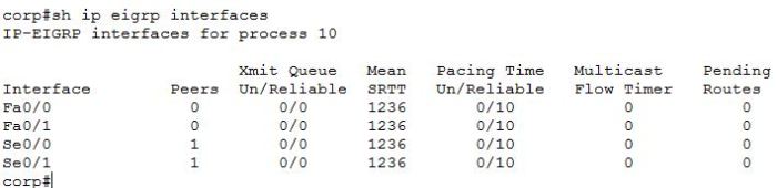
corp#sh ip ospf int s0/3/0
Serial0/3/0 is up, line protocol is up
Internet address is 192.168.1.1/30, Area 1
Process ID 1, Router ID 192.168.2.1, Network Type POINT-TO-POINT, Cost: 64
Transmit Delay is 1 sec, State POINT-TO-POINT, Priority 0
No designated router on this network
No backup designated router on this network
Timer intervals configured, Hello 10, Dead 40, Wait 40, Retransmit 5
Hello due in 00:00:04
Index 3/3, flood queue length 0
Next 0x0(0)/0x0(0)
Last flood scan length is 1, maximum is 1
Last flood scan time is 0 msec, maximum is 0 msec
Neighbor Count is 1 , Adjacent neighbor count is 1
Adjacent with neighbor 192.168.1.2
Suppress hello for 0 neighbor(s)
————————————————————————–
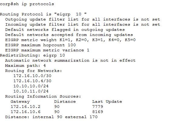
corp#sh ip protocols
Routing Protocol is “ospf 1”
Outgoing update filter list for all interfaces is not set
Incoming update filter list for all interfaces is not set
Router ID 192.168.2.1
Number of areas in this router is 3. 3 normal 0 stub 0 nssa
Maximum path: 4
Routing for Networks:
10.10.0.0 0.0.255.255 area 0
192.168.1.0 0.0.0.3 area 1
192.168.2.0 0.0.0.3 area 2
192.168.2.0 0.0.0.255 area 2
Routing Information Sources:
Gateway Distance Last Update
192.168.1.2 110 00:01:50
192.168.2.1 110 00:01:48
192.168.2.2 110 00:01:50
Distance: (default is 110)
————————————————————————
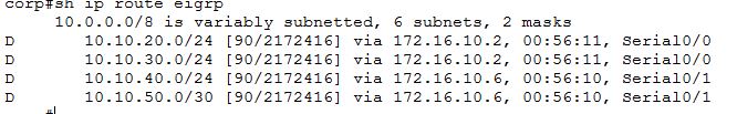
corp# sh ip route
Codes: L – local, C – connected, S – static, R – RIP, M – mobile, B – BGP
D – EIGRP, EX – EIGRP external, O – OSPF, IA – OSPF inter area
N1 – OSPF NSSA external type 1, N2 – OSPF NSSA external type 2
E1 – OSPF external type 1, E2 – OSPF external type 2, E – EGP
i – IS-IS, L1 – IS-IS level-1, L2 – IS-IS level-2, ia – IS-IS inter area
* – candidate default, U – per-user static route, o – ODR
P – periodic downloaded static route
Gateway of last resort is not set
10.0.0.0/8 is variably subnetted, 8 subnets, 2 masks
C 10.10.10.0/24 is directly connected, GigabitEthernet0/0
L 10.10.10.1/32 is directly connected, GigabitEthernet0/0
C 10.10.11.0/24 is directly connected, GigabitEthernet0/1
L 10.10.11.1/32 is directly connected, GigabitEthernet0/1
O 10.10.20.0/24 [110/65] via 192.168.1.2, 01:06:52, Serial0/3/0
O 10.10.30.0/24 [110/65] via 192.168.1.2, 01:06:52, Serial0/3/0
O 10.10.40.0/24 [110/65] via 192.168.2.2, 01:06:57, Serial0/3/1
O 10.10.50.0/24 [110/65] via 192.168.2.2, 01:06:57, Serial0/3/1
192.168.1.0/24 is variably subnetted, 2 subnets, 2 masks
C 192.168.1.0/30 is directly connected, Serial0/3/0
L 192.168.1.1/32 is directly connected, Serial0/3/0
192.168.2.0/24 is variably subnetted, 2 subnets, 2 masks
C 192.168.2.0/30 is directly connected, Serial0/3/1
L 192.168.2.1/32 is directly connected, Serial0/3/1
———————————————————————–
corp#sh ip ospf database
OSPF Router with ID (192.168.2.1) (Process ID 1)
Router Link States (Area 0)
Link ID ADV Router Age Seq# Checksum Link count
192.168.2.1 192.168.2.1 412 0x80000005 0x00f136 2
Summary Net Link States (Area 0)
Link ID ADV Router Age Seq# Checksum
192.168.1.0 192.168.2.1 398 0x8000000d 0x00053a
192.168.2.0 192.168.2.1 398 0x8000000e 0x00f745
10.10.40.0 192.168.2.1 398 0x8000000f 0x002542
10.10.50.0 192.168.2.1 398 0x80000010 0x00b4a7
10.10.20.0 192.168.2.1 393 0x80000011 0x00fd7b
10.10.30.0 192.168.2.1 393 0x80000012 0x008de0
Router Link States (Area 1)
Link ID ADV Router Age Seq# Checksum Link count
192.168.2.1 192.168.2.1 404 0x80000005 0x008425 2
192.168.1.2 192.168.1.2 405 0x80000007 0x0035f5 4
Summary Net Link States (Area 1)
Link ID ADV Router Age Seq# Checksum
10.10.10.0 192.168.2.1 410 0x8000000b 0x00f5d3
10.10.11.0 192.168.2.1 410 0x8000000c 0x00e8de
192.168.2.0 192.168.2.1 399 0x8000000d 0x00f944
10.10.40.0 192.168.2.1 399 0x8000000e 0x002741
10.10.50.0 192.168.2.1 399 0x8000000f 0x00b6a6
Router Link States (Area 2)
Link ID ADV Router Age Seq# Checksum Link count
192.168.2.1 192.168.2.1 404 0x80000005 0x00aff6 2
192.168.2.2 192.168.2.2 406 0x80000007 0x00d02e 4
Summary Net Link States (Area 2)
Link ID ADV Router Age Seq# Checksum
10.10.10.0 192.168.2.1 410 0x8000000b 0x00f5d3
10.10.11.0 192.168.2.1 410 0x8000000c 0x00e8de
192.168.1.0 192.168.2.1 400 0x8000000d 0x00053a
10.10.20.0 192.168.2.1 395 0x8000000e 0x000478
10.10.30.0 192.168.2.1 395 0x8000000f 0x0093dd