Cisco 8.4+ Enable ‘Port Forwarding’ on GNS3

Using GNS3, the ASA 5520 has an ‘outside’ address of 192.168.254.247

The XP1 VM has been set up with Abbyss Web Server, running on Port 8080.  You want all traffic from the 254 network to be able to reach the web server.

(Note, this is STATIC NAT, not DYNAMIC, because you have an individual host for the web service.


ASA8-4basic

Step 1:  Create a network object, and define its IP address:

ciscoasa(config)# object network outside-inside-web-server
ciscoasa(config-network-object)# host 192.168.1.100

Step 2 (still within network object) add your NAT statement
ciscoasa(config-network-object)# nat (inside, outside) static interface service tcp 8080 8080

Step 3: Define an access list allowing traffic from
ciscoasa(config-network-object)# access-list OutsideToWebServer permit tcp any host 192.168.1.100

(Note 1: the port is put in twice because it is source and destination port. You could translate the port here, but for a web server, source and destination port will be the same.)

(Note 2: The NAT statement and ACLis configured within the network object configuration)

Step 4: Apply the access list to the outside interface:

ciscoasa(config)# access-group OutsideToWebServer in interface outside

You should now be able to get to the web server anywhere on the ‘external’ network, which in this case, as it’s a lab, using GNS3, will still be your internal network.
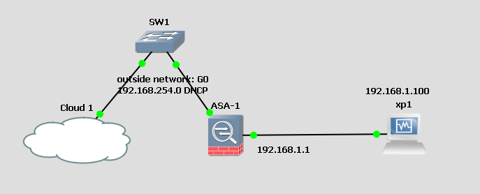


Cisco ASA 8.4+ on GNS3 – Basic configuration.

Setting up a test configuration on GNS3 with an ASA firewall is possible.

The first step is to create the ASA, which is created in QEMU. Instructions here:

http://www.xerunetworks.com/2012/02/cisco-asa-84-on-gns3/

And here, while it lasts, with file downloads:  http://srijit.com/use-cisco-asa-8-4-gns3/

Once you have your ASA, drag and drop it in to your workspace.

++++++++++++++++++++++++++++++++++++++++++++++++++++++++

The first basic configuration: Dynamic (many internal hosts to a single or range of external addresses)

You have an internal network: 192.168.1.0 , and an external network: 192.168.254.0 , gateway 192.168.254.2

Although the external network is on a non routed network, it could be a public IP, but it is set up within a network.

Step 1.

Create a new GNS3 project, and add a switch, a virtualbox VM, a cloud, and ASA, as in this diagram: (note, the switch is only there because you can’t connect anything directly to the cloud interface.)

ASA8-4basic

Step 2 Configure the outside and inside interfaces:

interface GigabitEthernet0
 nameif outside
 security-level 0
 ip address 192.168.254.247 255.255.255.0
!
interface GigabitEthernet1
 nameif inside
 security-level 100
 ip address 192.168.1.1 255.255.255.0

(Note: Interfaces must be named using the nameif command, and if you use the inside and outside nomenclature, the security levels will automatically be set)

Note that the higher the security number, the more trusted the interface. Hence Outside is 0, inside is 100.)

Step 2 Configure the default route. Nothing will work without it.

route outside 0 0 192.168.254.2  (The default router on this network)

Step 3 Configure NAT. (Very different from IOS)  You create an object and assign properties to it.
object network inside-subnet
subnet 192.168.1.0 255.255.255.0
nat (inside,outside) dynamic interface

(note that you use the interface name, (inside,outside0 not g1/0, etc)

You will now find that you can get to the internet from the virtual machine. (which is configured with the IP 192.168.1.100 and gateway 192.168.1.1)


ICND1: Connect to switch -Console, Telnet and SSH

To connect a switch to a PC to view console, do the following: (There is no other option initially except the console, but then you can set up SSH and Telnet

  1.  Connect DB9 to Cons port on router
  2. Connect Serial cable to PC, or via adapter if no serial cable
  3. Once you have putty working, create a management VLan:

en
conf t
vlan 100
int vlan 100
ip address 192.168.1.1 255.255.255.0

exit

int fa0/1
switchport mode access
switchport access vlan 100
exit

If you plug in a PC and configure the NIC with the correct IP, you should be able to ping.

The next stage is to configure Telnet:

line vty 0 4
login
password cisco

or

line vty 0 4
login local
exit

username steve privilege 15 password happy

you will also need an enable password:

enable password ecstacy

======================================================

SSH is more complicated:  (The following were copied from the absolutely excellent Geekstuff website: http://www.thegeekstuff.com/2013/08/enable-ssh-cisco/

After having set the management VLAN, you need to

  1. Set hostname and domain name
    # config t
    (config)# hostname myswitch
    (config)# ip domain-name thegeekstuff.com
  2. Generate SSH keys
    myswitch(config)# crypto key generate rsa
     The name for the keys will be: myswitch.thegeekstuff.com
     Choose the size of the key modulus in the range of 360 to 2048 for your
       General Purpose Keys. Choosing a key modulus greater than 512 may take
       a few minutes.
    
    How many bits in the modulus [512]: 1024
     % Generating 1024 bit RSA keys, keys will be non-exportable...[OK]
  3. Line vty set up:
    # line vty 0 4
    (config-line)# transport input ssh
    (config-line)# login local
    (config-line)# password 7
    (config-line)# exit
  4. Do the same for the console
    # line console 0
    (config-line)# logging synchronous
    (config-line)# login local
  5. Create username and password
    myswitch# config t
    Enter configuration commands, one per line.  End with CNTL/Z.
    myswitch(config)# username ramesh password mypassword
  6. Create enable password, if you haven’t already
    myswitch# enable secret myenablepassword
  7. Make all passwords not visible in sh run
    myswitch# service password-encryption


ICND 2: Etherchannel

Etherchannel sample configuration:

int range fa0/1 – 2
switchport mode trunk
switchport trunk encapsulation dot1q
channel-group 1 mode (Active-LACP Desirable – PAgP) (The most common seems to be active, as PAgP is Cisco Proprietary)

You can now configure the Port Channel as if it were a single interface:

int port-channel 1
switchport mode trunk
switchport trunk allowed vlan 1,2,3

Or shutdown, etc.

To view result:  sh etherchannel port-channel

Tells you which individual switchports are in the group, etc, and also the protocol – LACP eg

sh etherchannel summary gives you a line by line list of port channels.